Deferred Shading in OpenGL ES 3, Part II: Lighting
24 Sep 2014 •Continuing down the rabbit hole, it’s time to talk about lighting, arguably the most important aspect of our deferred renderer. Possibly the greatest argument for deferred shading has always been the ability to render a scene with hundreds or thousands of lights (each with a small area of effect) and achieve the same performance as just a few lights illuminating a scene using a forward renderer. The reason, of course, being that the deferred renderer performs light calculations only on final fragments that end up on the screen and not on every single point on every surface in the viewing frustum, as is the case with traditional forward shading.
Alas, I will not try to explain every concept or go into much detail for the simple reason of there being much more worthwhile resources on the topic; I will simply present my gathering of solutions, many of which are from fellow graphics programmers, along with what I believe to be the most noteworthy challenges in this here implementation of a deferred renderer using OpenGL ES 3.0.
Assuming the G-buffer has been properly set up and populated with valid data, we can build on top of that dataset and add simple directional and point lighting to our scene. The first step we need to take is to create a frame buffer that will hold lighting information for the frame being rendered, known as the light accumulation buffer. We only need a single color attachment on this buffer and in our case an RGBA8888 buffer will do nicely. This frame buffer also needs to add the G-buffer's depth and stencil buffers as attachments. We'll see further ahead how those buffers will be used to eliminate certain visual artifacts as well as increase performance.
Let's start simple and look at a directional light first. A directional light will affect every fragment on the screen, hence a full-screen pass over all pixels being displayed would be the way to go. We can utilize a screen-aligned quad covering the entire [-1.0, 1.0] range of normalized device coordinates to measure the directional light's contribution to the light accumulation buffer. During this pass we can turn off depth testing and writing for a minute performance gain. But more importantly, we need to enable additive blending (src.rgb + dst.rgb) so that all light contributions directly add to the contents of the buffer, resembling one of the key characteristics of light.
Below are the shaders that calculate per-fragment ambient, diffuse, and specular components for a given directional light using the Phong shading model. Note that the _Position attribute passed in to the vertex shader is one of the four vertices of a quad spanning [-0.5, 0.5]. Therefore, simply doubling each vertex position is sufficient for outputting the required position in normalized device coordinates. The NDC position along with UV texture coordinates are interpolated and sent along to the fragment shader.
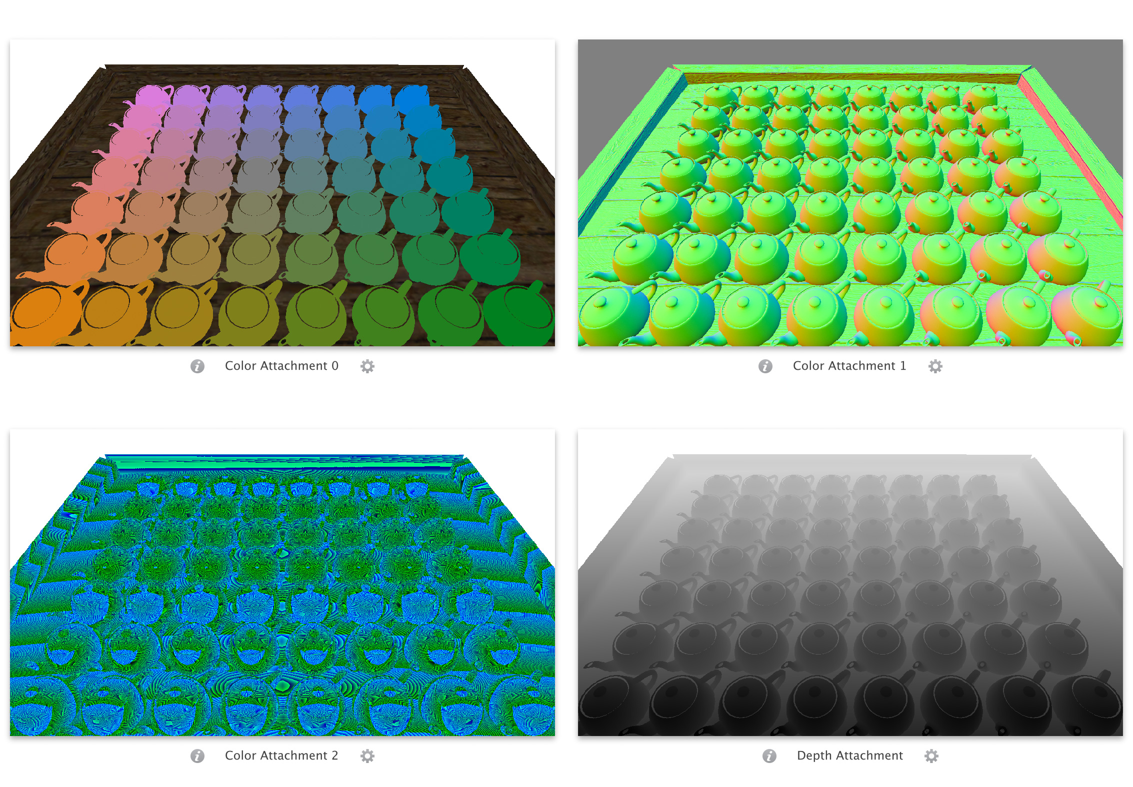
As you can see, G-buffer's color attachments from the previous render pass are fed to the fragment shader as texture samplers. The shader then extracts diffuse color, specular factor, normal, and depth from these textures. Fragment normal is scaled and biased to remap back to [-1.0, 1.0], while depth is reconstructed from the 32 bytes of data sampled from the texture (unpack_depth takes care of this using a simple dot product). At this point, the fragment's world-space position can easily be restored using the inverse projection view matrix (transforming from clip space to world space) followed by homogenization. Diffuse color and specularity are usable straight-up.
The lighting calculations in the shader are nothing out of the ordinary. It might just be helpful to know that the directional light's properties are packed into a 4x4 matrix and passed in as a uniform, along with _EyePosition which stores the world-space position of the camera. Fragment color is output to the RGB channels of the buffer, while the alpha channel is used as a simple - but not necessarily cheap - way of zeroing out light contributions where surfaces are not present.
If you recall, the color attachment storing normals in the G-buffer is cleared such that the default normal read from the buffer where no surface has been rendered is a vector of length zero. Since this program is executed on a full-screen quad, the dot product ensures that no color information is added to the light accumulation buffer for such fragments. In presence of geometry, however, unit normals will yield an alpha value of one. In practice it might be faster to check the length of the normal (or better yet, store a flag in the alpha component of the normal buffer which remains unused at the moment) and not go through any of the above calculations in case of no surfaces present. Then again, dynamic branching in the fragment shader might actually turn out to hurt performance more than the approach seen in the program above. Fortunately, a simple benchmark of the directional lighting pass using the two solutions described will give us a definitive answer.
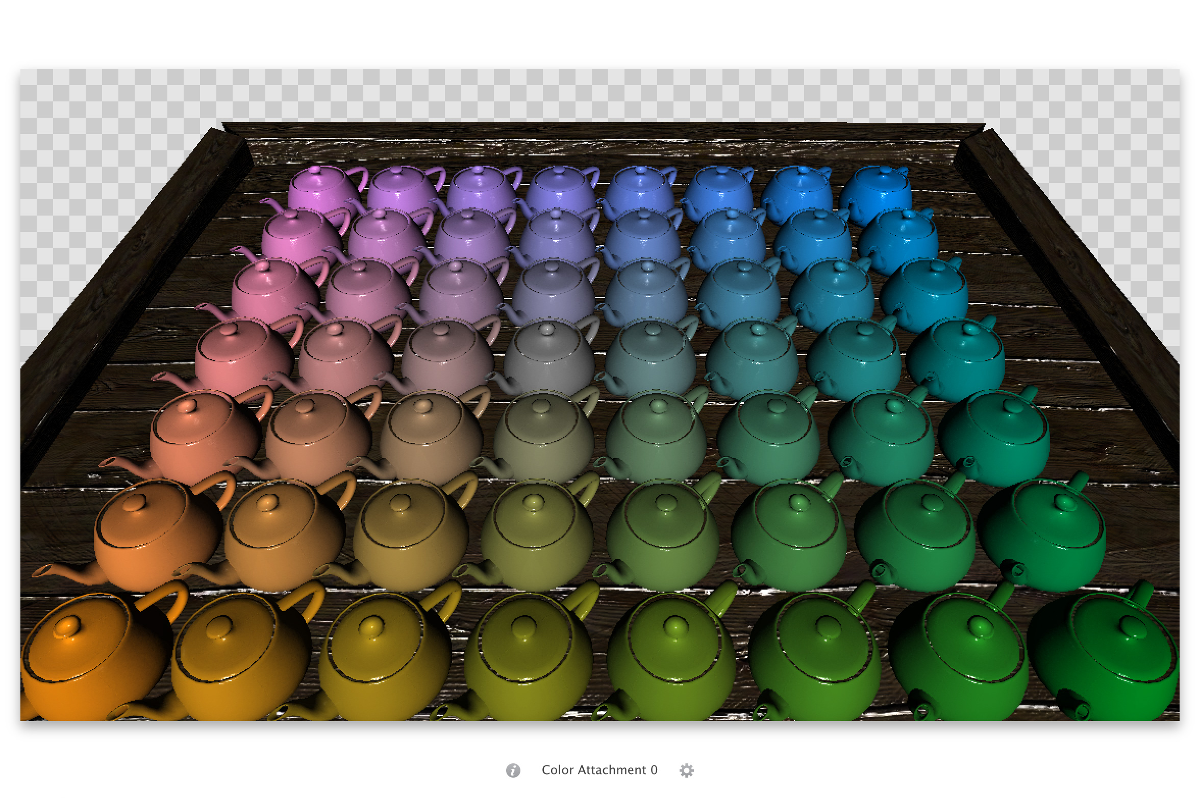
Below is what the light accumulation buffer holds after running the pass for a single directional light. Note that, while in most implementations this buffer stores grayscale values of light contributions only, I decided to take into account surface colors at the time of performing lighting calculations in order to eliminate an extra pass close to the end of the pipeline that would solely multiply diffuse colors with accumulated light values per fragment using a full-screen blit. Also worth noting are the transparent corners of the image which correspond to normals of length zero due to lack of geometry, and the perhaps not-so-apparent normal and specular mapping on most surfaces.
Adding point lights to our renderer requires a bit more setup. Since point lights are omni-directional, the best way to calculate their lighting contributions to a scene is to render a sphere mesh and perform deferred calculations in screen space, similar to a directional light. The sphere doesn't need to be high poly, of course, just as long as it looks relatively curved in the proper scale. The real power behind deferred shading becomes apparent when many lights each with a small area of effect contribute to illuminating a scene. Thankfully, our point lights - resembling light sources in the real world - have attenuation properties, which gives us the advantage of being able to render a finite sphere knowing that fragments that fall outside the sphere are not affected by the light source and therefore don't add to the computations on the GPU.
The light attenuation model we're using is based on the one presented by Tom Madams in his blog post, which is also shown here for reference. In the equation below, d is distance from the light source while r is the initial radius of our spherical light, a value that can be tweaked in order to increase the area of effect of a point light. The result is the attenuation factor which will be multiplied by a given light's contribution on any surface.
Having this in hand, we can calculate a maximum radius for our point light where it is known that any pixel falling outside this range will have contributions less than a certain threshold. A safe value to use is 1 / 256, since each color channel in a 32-bit color buffer will ultimately store 256 discrete values. The code snippet below returns the radius described above for a point light based on its intensity, diffuse color, and attenuation factors. For an explanation of how this formula came to be, visit Etay Meiri’s second tutorial on deferred shading.
float dynamic_radius_for_point_light(const Light& light)
{
    // Finds the optimal radius for a point light, allowing the maximum
    // channel of the light color to drop below 1/256 right at the edge

    const float maxChannel = Mathf::Max(Mathf::Max(light.DiffuseColor.x, light.DiffuseColor.y), light.DiffuseColor.z);
    const float c = light.ConstantAttenuation;
    const float l = light.LinearAttenuation;
    const float e = light.QuadraticAttenuation;
    const float i = light.Intensity;

    return (-l + Mathf::Sqrt(l * l - 4 * e * (c - 256 * maxChannel * i))) / (2 * e);
}
If at this point we render the sphere mesh straight up, we will notice a couple of anomalies. First off, should the camera enter a point light's spherical bounds, the light and its contributions will disappear from the scene - since front faces are no longer in the camera's frustum. If we disable culling altogether we will get half the contribution once inside the sphere as opposed to viewing the light sphere from outside. We could get away with only rendering back faces on the sphere mesh, but we will still have the problem of certain surfaces being unnecessarily included in lighting calculations. Those are surfaces that when projected to screen space sit behind a light sphere yet in world space lie completely outside its bounds. In theory, their distance from the light source will prevent them from being lit - due to attenuation, - but we will still pay for the extra overhead of performing their lighting calculations.
An elegant solution to this problem is described in Etay Meiri’s third tutorial in his deferred shading series. The basic idea is to use the stencil buffer to mark the fragments that lie inside the light sphere in an initial pass, then render the point light mesh while using the stencil buffer as a mask to point out the pixels that need to undergo lighting calculations. To set this up, we need to disable depth writing while keeping depth testing enabled, and turn off face culling so we can make use of the stencil operation on both front and back faces. The stencil test will be set to always succeed, while the stencil operation for back-facing polygons is configured to increment the value in the stencil buffer when the depth test fails. Similarly, the stencil operation for front-facing polygons will decrement the value in the stencil buffer when the depth test fails. Below is how the stencil buffer configuration will look in code. Of course, clearing the stencil buffer beforehand is also in order.
glEnable(GL_STENCIL_TEST);
glStencilFunc(GL_ALWAYS, 0, 0xFF);
glStencilOpSeparate(GL_BACK,  GL_KEEP, GL_INCR_WRAP, GL_KEEP);
glStencilOpSeparate(GL_FRONT, GL_KEEP, GL_DECR_WRAP, GL_KEEP);
For each point light illuminating the scene, the above setup is followed by rendering the light sphere with a minimal program that has no color output (the fragment shader is empty and color mask is used to turn color writing off). After running this pass, the stencil buffer will hold non-zero values for fragments inside the light sphere, and zeros everywhere else. The next step clearly is to render the sphere mesh, this time using the proper point light shaders, while setting the stencil test to pass only if the value in the stencil buffer is not equal to zero. This can be achieved using glStencilFunc(GL_NOTEQUAL, 0, 0xFF);. There is no need for depth testing or writing, and we want to render back faces only (turning on front face culling) while using additive blending. The result is point light illumination that is free of visual artifacts and only executes on fragments that the light visibly contributes to. Below are the shaders responsible for calculating Phong shading for a given point light in our deferred renderer.
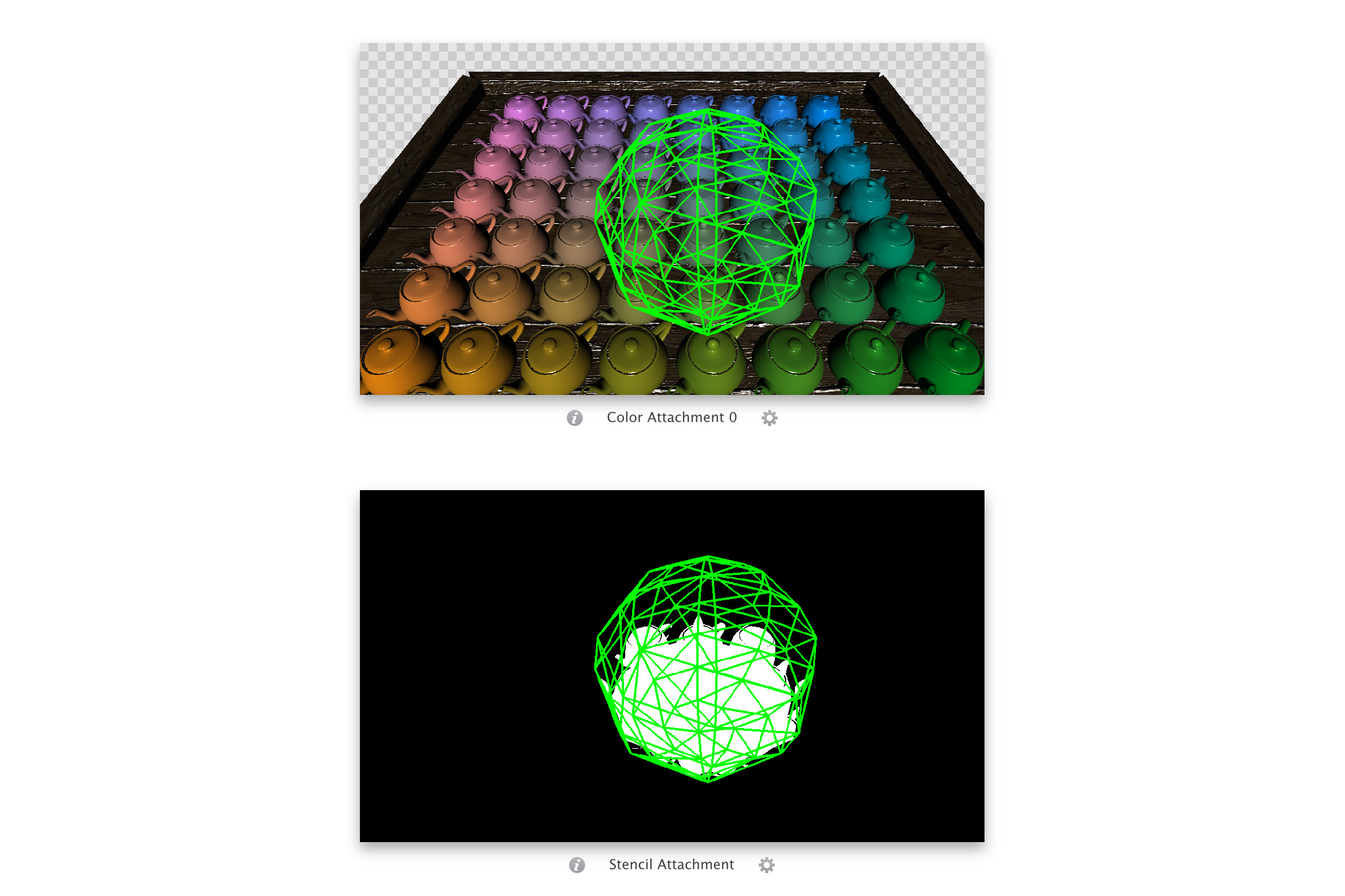
The vertex shader should be self-explanatory based on descriptions of shaders from previous passes. The fragment shader is also quite similar to that of the directional light pass, with the exception of attenuation being factored in. The screenshot below shows the state of stencil and color buffers after running the above two passes for a single point light, positioned just above one of the teapots closer to the center.
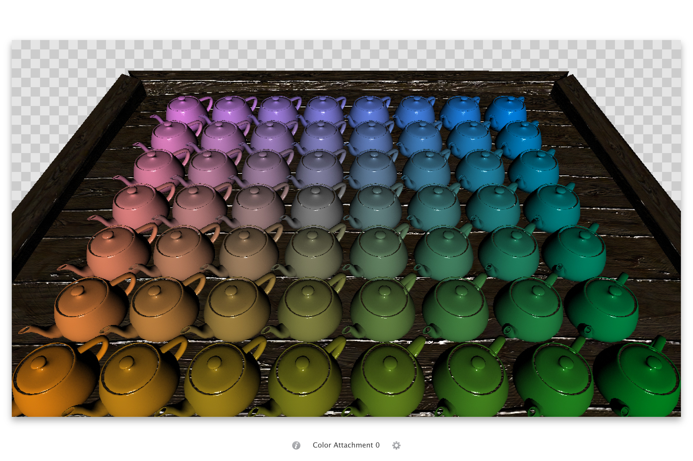
The final result of one directional light and thirty two point lights (one directly above every other teapot) illuminating the scene is the light accumulation buffer as pictured below. Just as a means of comparison, while rendering our sample scene using a release build on an iPhone 5S running iOS 7.1.2, the point lights altogether took 6.49 ms of the frame time, while the single directional light pass took 2.31 ms to execute.